STÖBER POSIDYN SDS 4041 Servo Drive Repair and Functional Testing
When an industrial servo drive fails, replacing damaged electronic components is only part of the repair.
The real objective is to determine where the failure is located, repair the affected circuitry, and then verify that the drive can operate correctly again under controlled conditions.
This STÖBER POSIDYN SDS 4041 is a good example of that process.
At Servo Motors Adjust, the repair involved electronic diagnosis, inspection of the power stage and subsequent functional testing of the repaired drive.

The STÖBER POSIDYN SDS 4041
The unit received in our workshop was a STÖBER POSIDYN SDS 4041 servo drive.
According to the drive nameplate, the unit is designed for:
- Input supply: 3 × 230–480 V AC
- Nominal output current: 3 × 6.0 A
- Peak output current: 3 × 12.0 A
- Protection class: IP20

For industrial equipment that has been operating reliably for many years, repairing the existing drive can be particularly valuable when maintaining compatibility with the original motor, machine configuration and control architecture.
Electronic Diagnosis
The first stage of the repair is not simply replacing components.
It is understanding which section of the drive has failed.
Once the STÖBER drive was opened, the internal electronic assemblies and power section could be inspected and tested.
The internal construction includes the control electronics, power supply circuitry, DC bus components and power semiconductor stage responsible for controlling the motor.
The investigation identified damage associated with the power electronics.
This distinction is important.
A failed semiconductor device can be the visible consequence of a failure, but the component itself does not necessarily explain why the failure occurred.
Unless sufficient evidence exists to establish the root cause, the technically correct approach is to separate:
what was found
from
what may have caused it.
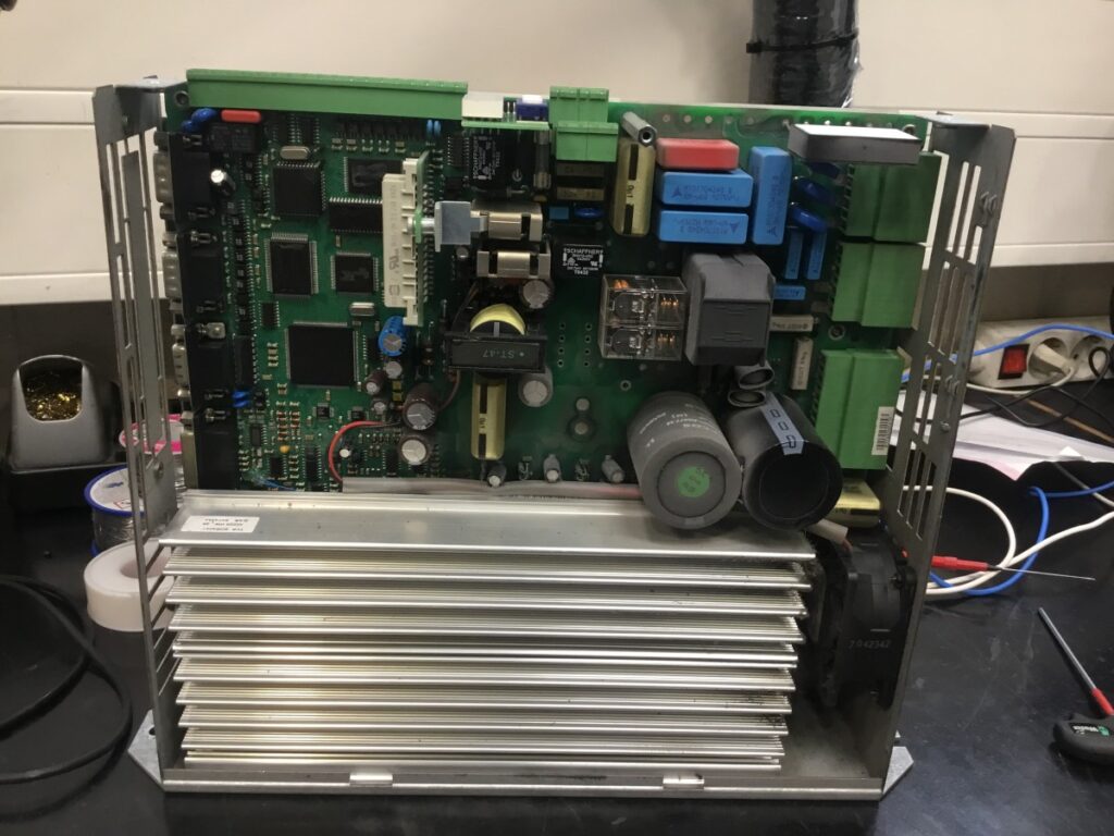

Inspecting the Power Stage
A closer examination of the electronics showed damage in the power semiconductor section.
The photographs taken during the repair provide direct physical evidence of the affected area.
Power-stage failures require particular attention because replacing the visibly damaged device alone may not be sufficient.
Associated circuitry around the semiconductor stage must also be evaluated before the drive is returned to operation.
This is especially important in servo drives, where the switching devices form part of a complete control system involving the DC bus, gate-control electronics, current measurement and motor feedback.


The Power Module
The power module installed in this unit was identified as an:
Eupec EconoPACK BSM25GD120DN2E3224
This module forms part of the drive’s power conversion stage.
In the photographs from the repair process, the internal construction of the module can be clearly seen after opening it.
This gives a particularly interesting view of a component that normally remains completely hidden inside a working servo drive.
Rather than treating the drive simply as a black box, examining the power electronics allows the failure to be approached at component and circuit level.

Repair Is Only Half of the Job
Replacing or repairing the defective electronics does not by itself demonstrate that the servo drive is ready to return to production.
After an electronic repair, the important question becomes:
Can the drive correctly control a servomotor again?
This is where functional testing becomes an essential part of the repair process.
A drive that powers up without an alarm has passed only one stage of verification.
For a servo drive, correct operation also involves the interaction between:
drive → power stage → motor → feedback → control loop
For that reason, wherever technically possible, the repaired drive should be tested as part of a working motion system rather than being evaluated only as an electronic assembly.

From Electronic Repair to System Validation
Servo drive repair should not finish at the soldering bench.
There are several different levels of verification:
Electronic verification
Checking the repaired circuits and power electronics.
↓
Power-up verification
Confirming that the drive starts correctly and that no immediate abnormal condition is detected.
↓
Communication and parameter verification
Checking interaction with the drive software and monitoring environment.
↓
Motor operation
Running the drive with a compatible motor.
↓
Functional validation
Confirming that the drive, motor and feedback system operate together correctly under the conditions reproduced during testing.
Each stage provides additional evidence about the condition of the repaired unit.
Why Functional Testing Matters
In industrial maintenance, the objective is not simply to return a drive that powers up.
The objective is to return a repaired unit with evidence that its functionality has been checked.
This distinction becomes especially important with servo systems because the drive does not operate independently.
Its real function only becomes apparent when power electronics, control electronics, motor and feedback are working together.
A successful bench test cannot reproduce every mechanical load or operating condition of the customer’s machine. However, it provides substantially more information than a simple power-on test and helps reduce uncertainty before the repaired unit is reinstalled.
Final Technical Conclusion
This STÖBER POSIDYN SDS 4041 repair illustrates an important principle in industrial electronics:
finding and replacing the damaged component is not the end of the repair process.
A complete approach combines electronic diagnosis, inspection of the affected power stage, repair of the identified fault and subsequent functional testing.
In this case, the repair process progressed from a damaged power-electronics section to controlled motor operation after repair.
That final verification is what connects an electronic repair with the actual purpose of the equipment: controlling motion reliably again.
At Servo Motors Adjust, our objective when repairing servo drives and servomotors is not simply to make the equipment power up again, but to verify its operation as far as the available test configuration allows.
Repair the electronics. Test the function. Verify the motion.


