Real case of two Schneider Electric servomotors from the same company, one of them with following error and the other one with vibrations.servo-user1 de June de 2022
Through vibration analysis, companies can plan in advance the maintenance of their servomotors to avoid any forced downtime.
A good vibrations control method is much less expensive than simple scheduled replacement program. Nowadays, many companies have replacement programs. This means replacing all the components and bearings whether they are worn (deteriorated) or not.
This can be significantly more expensive and inefficient in comparison with the identification processes of worn parts.
The most important reason for a vibration analysis is that it helps you to detect problems before they become unexpected catastrophic failures, economic losses and production delays.
We are going to describe the real case of two Schneider Electric servomotors from the same company, one of them with following error and the other one with vibrations.
In the video you can see two servomotors – one of them producing more vibration (noise) than the other.
As you have seen in the video there is a servomotor labelled “servomotor produces vibrations” which does not show vibration problems while the other with following error does produce vibrations.
In the following pictures you can see the spectra of the two servomotors and our technicians detect harmonics in one of them on the outer track and it is the servomotor that gives the following error.
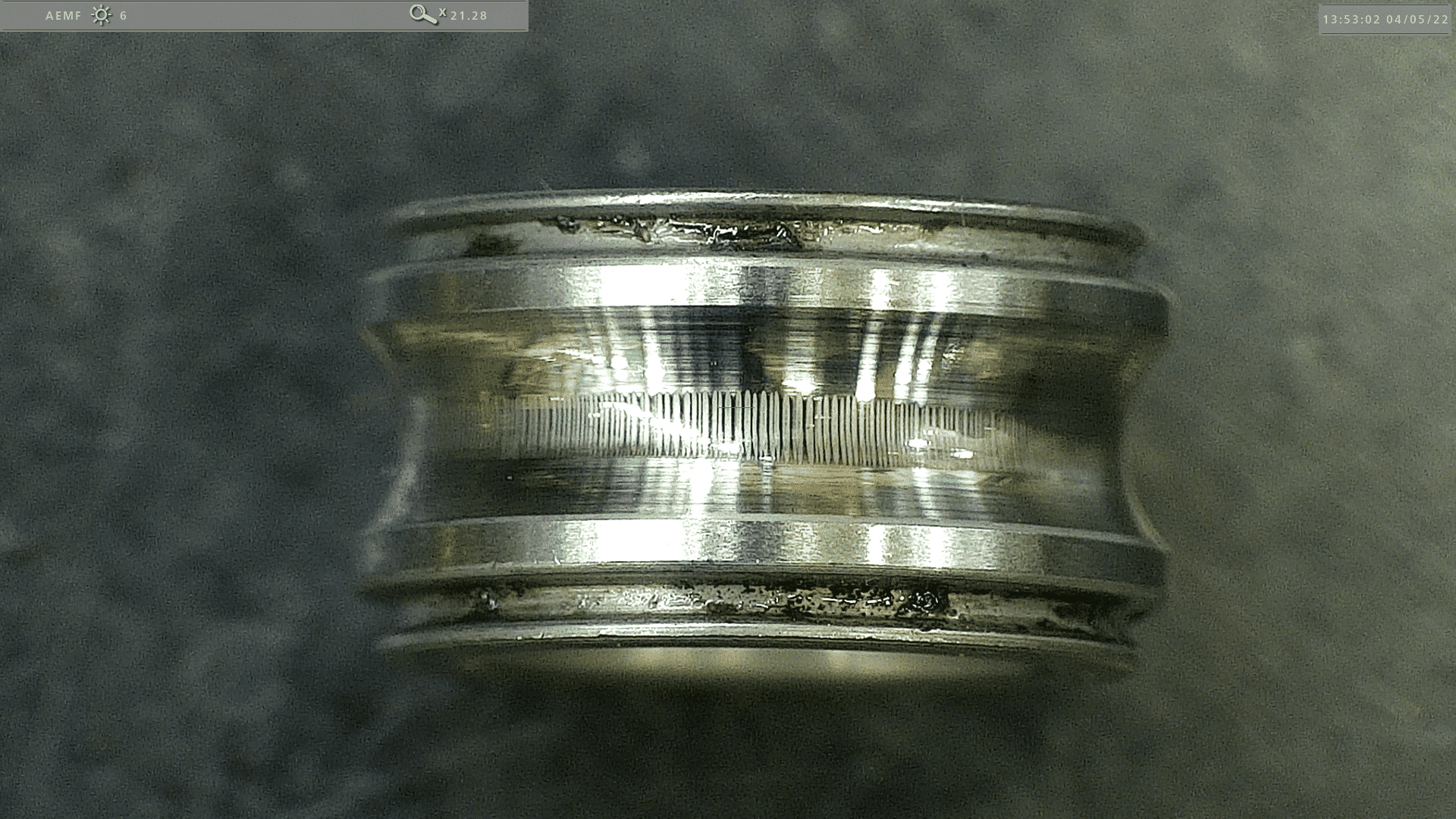
During the disassembly process and bearings analysis our technicians observe electrical current (fluting) in the rear bearing where the encoder is located.
In the following images we observe the NSK 6201 ZVbearing where we can see fluting in particular where the damage is caused by the electrical current that makes marks on the outer and inner tracks.
What are bearing currents and what causes them?
Pulse-width modulation is a fundamental operating principle of variable frequency drives (VFDs), but the high-frequency switching that delivers pulses of voltage from the drive to the motor can cause bearing currents — high-frequency currents that flow through the motor bearings, often leading to damage and premature failure.
To achieve pulse-width modulation, insulated gate bipolar transistors (IGBTs) in the variable frequency drive switch on and off rapidly to create a simulated sinusoidal AC waveform. Because the power is delivered in pulses, rather than as a true sine wave, the power is never balanced — that is, the sum of the three phases of power supplied to the motor is never equal to zero.
Imbalanced voltage
And this imbalanced voltage is referred to as common mode voltage (CMV), and it is one of the primary causes of bearing currents in motors driven by VFDs.
The fast switching time of the IGBTs creates parasitic capacitance, which causes capacitive coupling between the stator and rotor. This capacitive coupling induces a voltage (due to the common mode voltage caused by the drive) across the air gap between the stator and rotor. As the voltage searches for a path to ground, it travels through the motor shaft (which is connected to the rotor) and across the bearings.
Lubrication in the bearing normally acts as an insulator, but because the common mode voltage has a very high rate of change, known as dV/dt (due to the switching of the IGBTs), it can easily exceed the breakdown voltage of the lubrication — that is, the voltage at which the lubrication no longer acts as an insulator.
When this happens, a burst of current is released, known as capacitive discharge current.